1. Pre-installation Inspection (Must be Conducted)
1. **Flow Verification**
The valve body is cast with a **flow direction arrow**, which must be exactly consistent with the normal flow direction of the medium; if installed in the reverse position, the backflow function will be completely lost and the valve disc will be severely damaged by the impact.
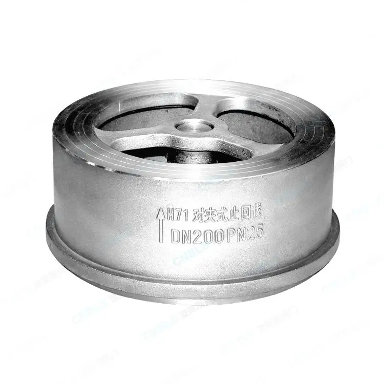
2. **Valve and Pipeline Inspection**
- The exterior is free of cracks, and the valve disc operates flexibly without any sticking. Before installing the valve at a pressure of ≥ 1.0 MPa, perform strength tests and sealing pressure tests on the shell.
The sealing surfaces of the flanges are smooth, without scratches, rust or welding debris; the parallelism and concentricity deviation of the two flanges is ≤ 0.5mm. The distance between the flanges matches the thickness of the valve, and the flanges must not be forcibly pulled to align.
Clean the internal weld slag, rust and particulate impurities in the pipeline to prevent the valve disc from getting stuck and causing internal leakage.
3. **Accessory Matching**
The gasket material is compatible with the medium (water/oil/gas/acid/alkali), and its size is the same as the sealing surface of the flange; the bolt specifications and pressure ratings are matched with the pipeline, and flat washers and spring washers are prepared.
II. Installation Position Requirements (Single Petal/Double Petal)
1. Horizontal pipe installation (most commonly used)
Double-leaf flanged check valve: Can be installed horizontally at will.
Single-leaf springless check valve: The valve shaft remains vertically upward (with the hanger facing upwards), ensuring that the valve disc closes smoothly under the force of gravity; when the valve shaft is horizontal or downward, it will not close tightly and will continue to leak internally.
2. Installation of Vertical Pipes
- The medium flows **from bottom to top**: Single, double-leaf, and spring types can all function normally.
- Medium flows **from top to bottom**: It is strictly prohibited to install single-leaf check valves without springs. Gravity cannot close the valve; only double-leaf models with strong springs can be used.
III. Specification for Fastener Tightening (Flanges, Gaskets, Bolts)
1. **Gasket Placement**
The gasket should be centered and tightly adhered to the sealing surface without any skew or folding. Multiple gaskets shall not be stacked, and excessive application of sealant to seep into the valve and contaminate the valve disc is prohibited. All old gaskets must be replaced with new ones.
2. Center alignment
The valve is placed between the two flanges, with the valve body being perfectly coaxial with the pipeline, and there is no unilateral compression. It is strictly prohibited to forcibly align the pipeline with the flanges to prevent the valve body from deforming due to long-term uneven loading.
3. **Screw Tightening Method (Core Leak Prevention)**
Use the method of "crosswise diagonal tightening", applying force gradually in three stages. It is strictly prohibited to lock in one direction all at once.
If a torque wrench is available, tighten the flange according to the standard torque. If it is too loose, it will cause leakage; if it is over-tightened, it will deform the valve body and jam the valve disc.
After the system is flushed with water and pressure tested, and after a cold and hot circulation, recheck and retighten the bolts (the compression of the gaskets and the thermal expansion and contraction may cause loosening).
IV. Prohibitions for Straight Pipe Sections and Branching Pipes (Often Easily Ignored)
1. **Requirements for Pump Outlet Installation**
A straight pipe section of at least 6 times the nominal diameter is reserved at the front end of the pump outlet check valve to prevent turbulent flow from the pump from impacting the valve disc, causing water hammer, and resulting in poor closure.
2. **Restrictions on Elbow, Change in Diameter, and Valve Spacing**
It is strictly prohibited to install concentric or eccentric reducers immediately before or after the valve. Eddy currents will disrupt the operation of the valve disc.
Avoid 90-degree elbows. After the elbow, at least keep 3 to 5 times the pipe diameter of straight pipe section before installing the check valve.
It is prohibited to install butterfly valves and gate valves closely face-to-face. A short pipe should be added between the two valves for isolation to prevent the valve discs from interfering and colliding with each other.
3. **Valve Disc Movement Space**
There are no weld seams, pipe steps or joint protrusions within the swing range of the valve disc, ensuring no obstruction during full opening and full closing.
V. Load-bearing and Pipe Supports
1. The split-type valve cannot bear the weight of the pipeline; for large-diameter valves with a diameter of 200mm or above, independent pipeline supports must be added on both sides of the valve to eliminate the additional bending moments and stress deformations of the valve body.
2. For the thermal expansion and contraction of the pipeline, expansion joints must be provided. The expansion displacement should not be borne by the valve.
VI. Additional Requirements for Environment and Operating Conditions
1. Water hammer protection
High-head pumps and large-diameter pipelines are equipped with **slow-closing spring-type flanged check valves**, which help reduce water hammer impacts during pump shutdown and protect the pipelines and pump bodies.
2. **Low Temperature Freeze Prevention**
Thermal insulation and heating accessories are installed in environments below 0℃ to prevent the medium from freezing and causing the valve flap to jam or the valve body to rupture.
3. **Medium contains particles**
For sewage, coal powder and slurry pipelines, filters should be installed before the valves. Solid particles are highly likely to wear the sealing surfaces, resulting in permanent internal leakage.
VII. Strictly Prohibit Irregular Operations
1. Do not use it as a shut-off valve to frequently cut off the flow. If it is half-opened for a long time to erode the seal, it will quickly fail and cause internal leakage.
2. After installation, it is strictly prohibited to perform any welding or cutting operations near the valve body or flange. High-temperature deformation may cause damage to the seals and springs.
3. Prohibit unilateral force application and forced alignment. Also, prevent the pipeline stress from continuously acting on the valve body.
4. Do not install upside down or reverse the flow direction. Before operation, double-check the arrow direction.
VIII. Pressure Testing and Acceptance after Installation
1. Gradually increase the pressure, apply it in stages, and observe that there is no leakage from the flange gasket.
2. Forward water flow: The valve disc opens fully automatically, allowing smooth flow without any abnormal vibration or noise.
3. Cut off the upstream medium and observe that there is no backflow or obvious internal leakage at the downstream end of the pipeline.
4. Conduct a 24-hour recheck of the bolt tension and sealing condition.